|
Project History Although I didn't start building the EZ-Tuner until March 2000, the idea had been in the back of my mind for several years before then. |
|
|
Project History Although I didn't start building the EZ-Tuner until March 2000, the idea had been in the back of my mind for several years before then. |
|
I'd long wanted an autotuner that could handle 1500 Watts, because I have several amplifiers in my vintage radio collection, spread over several operating tables, and I was constantly running back-and-forth adjusting my manual tuner. Also, my old homebrew tuner was showing its age, and I knew it was going to have to be replaced or rebuilt before much longer.
|
Unfortunately, there are no commercial legal-power ham autotuners on the market. Most built-in transceiver autotuners are rated at 200 W or less, and most of those can handle VSWRs of only 3:1 or so. If I wanted a high power wide-range auto tuner, it seemed clear I had little choice but to build one from scratch.. |
|
Many of the best commercial autotuners, like the SGC-230, use relay-switched toroidal inductors and fixed capacitors. While these work well, it didn't seem practical to me to scale up the concept to the 1500 W level. My best bet seemed to be a conventional variable-capacitor tuner, controlled by stepper motors. Furthermore, I didn't like the idea of a fully automatic 1500 W tuner that "hunted" for a minimum VSWR using a trial-and-error search alogorithm. (And I was pretty sure my homebrew 8877 amp wouldn't like it either!) A manually tuned "memory" tuner with stored settings seemed less likely to lead to inadvertent amplifier damage.
|
|
About six months before I started on the project, I stumbled across the newly-released Parallax BASIC Stamp BS2sx. With 2000 program steps, 50 MHz clock speed, and 16 I/O ports, it seemed to have enough horsepower for my project. Also, I had used a BASIC Stamp in an earlier QRP project, and really liked its ease of programming, which for me was important. One big decision out of the way! |
|
I started the project by designing a stepper motor controller. Although one can buy commercial controller boards, most seemed to be too expensive, had too many unneeded features, or weren't suitable for RF use. For my design, I borrowed ideas on the basic waveform circuitry from a "Nuts and Volts" article, and added an auto-timeout feature and optically isolated motor drivers, which seemed like a good idea for strong RF environments. |
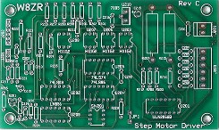
The 3x5 inch stepper motor controller circuit board was designed using "Circad 98," a great piece of software by Holophase, Inc., Shown here is a "Rev. C" board which has a nice silkscreened component legend and solder mask. |
|
Once the stepper motor drivers were built and tested, I started thinking about the features I wanted. I usually begin a homebrew project by sketching out the front panel, since playing with the imaginary knobs and switches on paper helps me focus on the features I really want. |
Here's the original front panel design, drawn at work during a boring committee meeting. |
Once I had a general idea of the specifications, I started writing the software code, an effort that took the better part of six months. To test and debug the code as it was being written, I lashed together a breadboard of the control circuitry, as shown below. The BS2sx microcontroller is buried under the rat's nest in the middle.
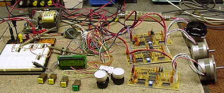
At this point in the project, I planned on using a roller inductor in the tuner (which is why there are three stepper motors in the photo.) Eventually, I decided on a switched fixed inductor to minimize losses and to facilitate rapid bandchanging. I wanted to change bands in seconds, and not wait for a rotary inductor to crank through its turns.
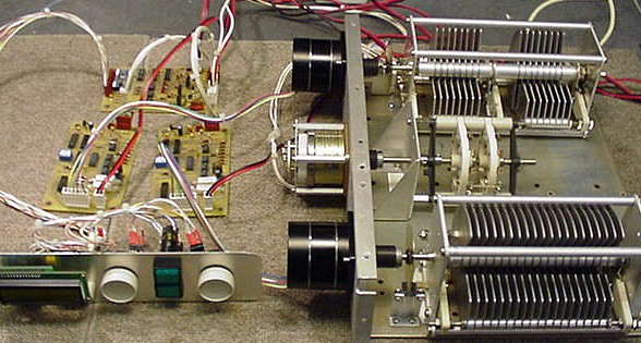
Once I had the software more-or-less working, I designed another PC board containing the BS2sx module, frequency counter, and relay drivers. Final testing of the completed controller circuitry was done using a mockup of the RF section, as shown below. For testing, I fabricated a temporary "front panel" out of sheet aluminum to hold the controls and mounted the switch and variable capacitors on a scrap aluminum plate.
Finally, it was time to start designing the RF section of the tuner, and this proved to be a much harder job than I'd anticipated. I started by bringing myself up to date on antenna tuner design, with several excellent QST and QEX articles by Bill Sabin, W0IYH, Dean Straw, N6BV, Frank Witt, AI1H, and others. There sure are a lot of subtleties for a device that only consists of two capacitors and an inductor!
I eventually settled on the basic T-network because of its versatility, but now I ran into a stumbling block. Virtually all the T-network tuners I saw used roller inductors, with continuously variable inductance.
My tuner, by contrast, was going to use a fixed inductor with an 11-position switch. What 11 inductances should I choose to maximize the matching range on all 9 HF bands, while also minimizing power loss (heating) and high peak RF voltages? I didn't even know how to go about answering that question.
By now, summer of 2001 had arrived, and I had three weeks to spend at our family vacation cabin in the Montana mountains. When I wasn't hiking in the wilderness or operating W8ZR/7 in the cabin hamshack, I had several hours a day to spend on the problem. Fortunately, I had N6BV's excellent computer simulation programs AAT.exe and TLA.exe, which could generate T-Network solutions for virtually any impedance. Unfortunately, for each impedance and frequency, there are about a zillion matching combinations of inductance and capacitance, each with different losses and peak voltages. I needed some way to sort through all that information, so I could pick out the eleven best inductances for my tuner.
Eventually, I was able to identify patterns in the T-Network solutions, which could be displayed in two frequency-independent graphs. One graph showed curves of the network values for different load impedances, and the other showed the corresponding network losses. Armed with these graphs, it was then a straightforward exercise to select my tuner inductances. (See the figures in April 2002 QST for details.)
By then, I could hardly wait to get back to Oxford to begin building the tuner. The actual construction only took about three months of weekends and evenings, followed by a month of software debugging and ironing out wrinkles. By the end of November 2001, the EZ-Tuner was finally completed!
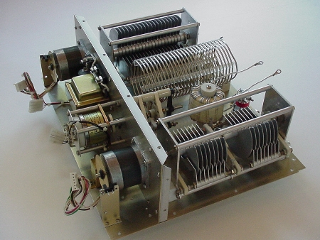
Here's the RF sub-assembly, prior to final wiring, ready to be mounted in the cabinet.
|
Want to see more? Click here! |
||
I welcome email comments and suggestions. Thanks for looking!