Circuit Description
(To follow this description, it will be necessary first to download and print the EZ-Tuner's circuit diagrams. Click HERE to download the diagrams)
The circuit diagrams of the EZ-Tuner are in five pages, with contents as follows:
|
CONTENTS |
|
|
Sheet 1 |
Interconnection diagrams, plug/connector IDs, wiring harnesses |
|
Sheet 2 |
Microcontroller circuit board, with BS2sx, relay drivers, frequency counter |
|
Sheet 3 |
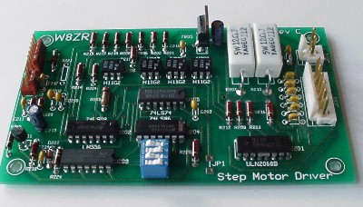
Stepper motor driver circuit board (2 required) |
|
Sheet 4 |
Front panel wiring, +5 V and +24 V power supplies |
|
Sheet 5 |
RF circuitry, with variable caps, inductor, wattmeter, and related components |
The circuitry of the EZ-Tuner is very straightforward. The variable capacitors are turned by two 11.2V unipolar stepper motors, and the bandswitch by a 24V rotary solenoid. Each stepper motor is controlled by its own printed circuit board, and these are in turn controlled by a printed circuit microcontroller board.
The microcontroller in the EZ-tuner is a Basic Stamp model BS2sx. The BS2sx is a PIC-based microcontroller that features a 50 MHz clock speed, 16 I-O ports, 2000 Bytes of on-board EEPROM, and a high-level Basic interpreter language. The BS2sx is conveniently programmed by uploading the code through an ordinary serial port.
A. Controller Organization: Sheet 1 shows the overall interconnection diagram for the EZ-Tuner. Separate +5V (regulated) and +24V (unregulated) power supplies provide power for the microcontroller circuits, and the relays, stepper motors, and rotary solenoid circuits, respectively. Note that these power supplies are completely isolated from one another, with separate ground returns. To keep RF currents out of the controller circuitry, the +5V ground is connected to the chassis at only one point, and the +24V ground is isolated from the chassis.
B. Microcontroller and Relay Driver Circuit: As seen in Sheet 2, most of the "horsepower" of the circuit is in the software controlling U104, the BS2sx, and as a consequence little external circuitry is required. Referring to the diagram, pins 1-4 of U104 are the serial port programming input to the BS2-SX and are connected directly to a rear-panel DB-9 connector. Pin 1, the SOUT port, serves double duty as an output port for the LCD serial data. Ports P0 - P8 interface to the front panel encoders, and pushbuttons. Port P4 has a dual function as the UP button sensor and the Speaker output (for the confirming beeps).
Ports P9-P11 control the In-line/Off-line DPDT vacuum relay, the External Capacitance relay, and the bandswitch rotary solenoid. The In-line/Off-line relay driver voltage from Port P9 is applied to the LED of opto-isolator U107, with R117 limiting the current through the LED to about 10mA. When the LED is illuminated, the darlington output stage of U107 conducts, turning on Q103, a TIP125 power darlington transistor, which ouputs a +24V control voltage to the relay. Diodes D109 and D110 protect Q103 from relay-induced inductive spikes. The operation of the the other relay driver and rotary solenoid circuits is identical.
J101 samples the RF drive from the EZ-Tuner input, and applies the signal to an input of the inverter U101a. Diodes D101-D104 condition the input signal to avoid voltage swings that could damage U101. The purpose of U101a, which has a high impedance CMOS input and a low-impedance output, is to buffer the signal at the input of U103, a high-speed decade divider. U103 divides the frequency by ten, and its square wave output is divided again by ten by U102, so that the frequency of the square wave appearing at Port P15 of U104 is equal to 1/100 of the frequency of the transmitted signal. This signal division converts an e.g., 30MHz signal to a 300 kHz square wave, which falls within the counter range of the BS2-SX. The actual frequency counting is done in software.
Ports P12-P14 provide output signals for the two stepper motor controller boards. P12 and P13 provide step pulses for stepper controllers, and P14 provides a TTL level specifying clockwise or counterclockwise direction. Note that a third stepper motor can be controlled from P11, which is also used to control the rotary solenoid. The circuit board was designed so that either a rotary solenoid or a stepper motor could be used to control the EZ-Tuner inductor, at the discretion of the builder. Changing from one to the other requires only a minor software revision.
C. Stepper Motor Driver Circuit: The circuit of Sheet 3 shows a general purpose controller for a unipolar (6 wire) stepper motor. The circuit has several switch-selected options that make it extremely easy to interface to any microcontroller. Some features of the stepper driver include:
1. Optical isolation between the motor driver circuit and the logic circuits, providing isolation from motor-induced noise and RF interference. The circuit is intended for use in strong RF environments.
2. An on-board timer that disconnects power from the stepper motor 0.2 seconds after the last control pulse has been received. This feature is used in the EZ-Tuner, but for other applications, the power-off feature may be controlled by the microcontroller or disabled completely.
3. Motor steps and direction are controlled by only two wires: (1) a step input, which can be a rising or falling edge TTL pulse or square wave; and (2) a rotation direction determined by a TTL HI (CW) or TTL LO (CCW) level.
4. An on-board +5V regulator, that can be used to power external control circuitry in applications that do not require complete optical isolation.
5. Stepper motors of from 5 - 28 Volts may be controlled, with up to 1A per phase.
Circuit Description: The stepper motor is controlled by U201, which consists of four hi-current (1.5A) switches in a single DIP package. Each section of U201 contains a built-in safety diode, which protects U201 from inductive motor spikes. Resistors R207 and R215 limit the current through the center tap of the motor windings for power supply voltages Vs that exceed the motor ratings; these resistors are jumpered if no current-limiting is needed. U210 is a +5 Volt regulator for the internal circuitry of U201. As described below, U210 can also be used (in other applications) to power the rest of the control circuit as well as any external circuits
The four sections of U201 are controlled by the open collector outputs of opto-couplers U203, U206, U207, U208. When the LEDs in the opto-coupler are illuminated, the output photo darlingtons conduct, driving low the inputs of U201 and disabling the respective motor windings.
Note that all ground connections on the output side of the opto-couplers are shown as earth grounds, whereas all the grounds on the input side of the opto-couplers are shown as chassis grounds. These separate grounds provide complete electrical isolation between the input and output sides of the opto-couplers to prevent interaction between the circuits. If this degree of isolation is not needed in other applications, then the two grounds can be jumpered together at JP1. By closing switch SW4, the regulated +5V from the output of U210 can then be used to power the controller logic circuits. The +5V also appears at pin 1 of J202, for use by external circuitry.
The sequencing waveforms for the stepper motor are determined by dual flip-flops U205a and U205b, in combination with XOR gates U204a and U204b. The four TTL outputs of U205a and U205b are applied to one set of inputs of NAND gates U202a-U202d. When the other inputs of these gates are HI, the gates just pass through the TTL input levels to the LEDs of U203 and U206-U208. When the other inputs of U202a-U202d are LO, the output of the gates is low. Thus U202a-U202d can be used to disable or enable the motor driver circuit, depending on the state of the control inputs.
There are three ways that gates U202a-U202d can be used to enable or disable the motor, depending on the settings of DIP switches SW2 and SW3. With both switches open, the output of XOR gate U204d is always HI, thus permanently enabling U202a-U202d. When SW2 is closed and SW3 is open, then a LO on pin 4 of J202 turns off Q201, which causes U204d to output a HI to U202a-U202d. When SW2 is open and SW3 is closed, then the state of XOR gate U204d is controlled by the output at pin 9 of U209b.
U209a and U209b are twin 555-type timers configured as a retriggerable monostable multivibrator. The purpose of these timers is automatically to enable the motor while step pulses are being received, and then to disable the motor after the step sequence is completed. The timer triggers on the initial motor step pulse appearing at the output of U204c, and outputs a HI at pin 9 of U209b. This output remains high for about 0.2 seconds after the last step pulse is received, a time constant set by R223 and C213.
The motor is stepped by TTL level pulses appearing on pin 5 of J202. XOR gate U204c is used to set the polarity of the triggering, according to the setting of SW1. The flip-flops trigger on either rising or falling edges of the input waveform; the EZ-Tuner uses rising edges.
Pin 3 of J202 is a limit detect output to the microcontroller. Stepper motors generally have an optical or mechanical switch that indicates when one end of rotation is reached (e.g., when a variable capacitor is fully meshed). Resistor networks R221, R222 and C211, C212 provide biasing and conditioning for this limit switch. In the EZ-Tuner, an optical interrupter is used to detect the end of rotation limit of the stepper motors. However, R221 is not used with the EZ-Tuner, because a pullup resistor for the LED sense line is already contained on the EZ-Tuner controller board.