Inside the EZ-Tuner
Construction Details & Hints for Builders
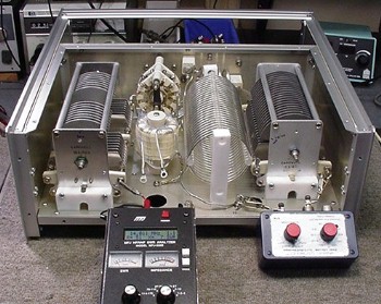
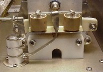
Because of its complexity, I designed the EZ-Tuner with ease of servicing in mind. (Wish I could say the same for most of my other homebrew projects!) The above view shows the front panel folded down for access to the stepper motors, rotary solenoid (which turns the inductor switch), and +24V power supply, which mounts on the sub-panel. As shown below, all RF components are housed in a shielded sub-enclosure. Should I need to replace any of these parts (knock on wood!) the rear panel detaches by unsoldering two wires and removing some screws.
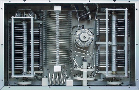
From left to right in the above view is the 35-492 pF output capacitor, the dual-coil inductance, the two-pole 11 position inductor switch, and the 19-202 pF (per section) split-stator input capacitor. A 4:1 toroidal transformer is mounted just behind the bandswitch, and behind it is a DPDT Kilovac vacuum relay, used for on-line/off-line switching. Barely visible behind the output capacitor are two 50pF high voltage fixed capacitors.
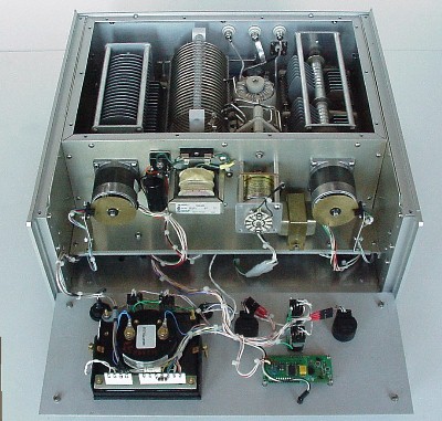
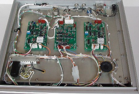
Below is a view of the chassis underside, showing the EZ-Tuner's three printed circuit boards: a microcontroller board (center) and two identical stepper motor driver boards. The PC boards mount on small tapped metal spacers, and connect via Molex-type connectors and headers. I took the precaution of making a few spare circuit boards, so that boards can be swapped in a few minutes.
The wiring harness uses teflon-insulated wire, which doesn't melt at soldering iron temperatures. Borrowing an idea from my old Collins rigs, I used all stainless steel hardware, with pan-head phillips screws. Also shown in the below photo are the +5V regulated power supply (left front), a small "beep" speaker (right front), and an RFI AC line filter (right rear).
Now, here are a few hints for builders and some more details about the EZ-Tuner's inner workings:
|
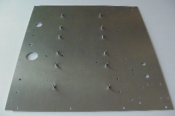
"Measure twice, cut once." It pays to heed the old carpenter's adage when doing metalwork. Drilling the aluminum chassis plate (right) was tedious, even with chassis punches and a drill press. The chassis plate has a total of 64 holes. The twelve threaded metal spacers are for mounting the three printed circuit boards. |
|
|
. |
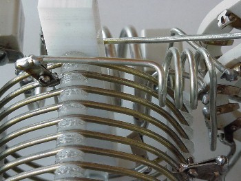
Setting the inductor taps is easy when using an MFJ-259B analyzer and the geometric resistance box (GRB) designed by Frank Witt, AI1H. Frank's neat little gizmo is basically a series of switched precision resistors, which simulate low or high resistance loads, up to a 32:1 VSWR. To set the taps, one attaches the GRB to the output of the tuner and the MFJ analyzer to the input. Then, after setting the variable caps to the calculated values for matching a 50 ohm load (allowing a few pF for stray capacitance), one simply moves the coil tap around until a 1:1 match is found. B&W coil taps make this a painless chore, since they mechanically clamp the inductor and are easily moved. When the left photo was taken, I was only trying to ballpark the tap locations. I tweaked the taps to their final positions after installing the back panel and compartment cover. After finding the final positions, I soldered the taps to the coils to assure a good low-resistance bond to the inductor |
|
Sometimes, the parts layout won't let you put a tap just where it's needed. In these cases, you can add a smidgen of inductance to the tap itself, as shown in the right photo. |
|
|
|
A half-century ago, the Tektronix Corporation elevated the humble terminal strip to an art form. The EZ-Tuner uses ceramic and silver Tektronix terminal strips (left), salvaged from old Tek oscilloscopes. You won't see these in your MFJ tuner! Click HERE to see the original 1958 patent on the terminal strips! It's important to use silver-bearing solder with these terminal strips to prevent the silver from unbonding from the ceramic. Tektronix thoughtfully attached little spools of the special solder to the chassis of their scopes, for use by service techs. Ahh, for the good old days! |
|
The right photo shows twin 50 pF ceramic 5 kV capacitors, which provide an extra 100 pF of output capacitance to the 492 pF variable capacitor on 160 meters. The ceramic caps are mounted on a small L-bracket affixed to the rear of the variable capacitor and are automotically switched into the circuit with a Jennings RF-3A vacuum relay. |
|
|
|
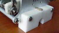
In a T-network, both the stator and rotor plates of both variable capacitors must be insulated from ground. I fabricated mounting blocks from teflon scrap I found on EBay and used Millen ceramic shaft couplers from my junque box to isolate the capacitor shafts. I knew I'd find a use for them one day! |
|
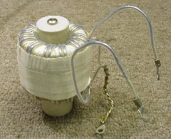
Shown at right is a closeup of the 4:1 bifilar-wound toroidal transformer, used to transform the unbalanced output of the tuner to a balanced output. The toroid is wound of #12 wire (insulated with teflon sleeving) on three Amidon T-200-2 (red) cores. The cores are wrapped with high-temperature fiberglass tape. Recent editions of the ARRL Handbook show a nifty antenna tuner with the toroid connected to the tuner's input, where it always sees a 50 ohm impedance. I finally ruled out that option, because it requires the toroid to always be in the circuit, even for unbalanced loads. |
|
|
Still want to see more? Click one of the boxes, below. |
||
I welcome email comments and suggestions. Thanks for looking!