|
A trip to the kitchen and two dishwasher cycles later, the grunge on the chassis came off nicely. (Funny how the meat loaf the next day tasted like burned resistor.) Shorn of all its components, however, the chassis' gouged tube socket cutout really looked awful.
|
|
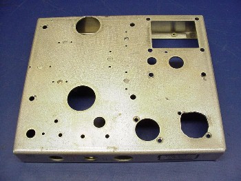
After two cycles in the XYL's dishwasher (using the pot-scrubber cycle), the chassis is beginning to look presentable.
|
|
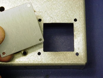
A new rectangular opening with a cover plate replaces the original gouged tube socket cutout.
|
|
Out came the nibbler and a file, and in a half-hour the cutout looked a whole lot better. A small aluminum cover plate provided the finishing touch. (Okay, I know, no one could see the original ugly hole with the cover plate in place. But I'd know it was there and I'd never be happy with the supply if I didn't fix it.)
|
|
There's nothing quite as classy as the silver-ceramic terminal strips from old Tektronix oscilloscopes, and I used several of them to mount the two diode rectifier banks. Twelve 1N4007 diodes (in four strings of three) replace the 5U4 and 5R4 rectifier tubes. The diodes lay between the Tektronix strips, and the whole assembly sits on a small piece of glass-epoxy circuit board.
|
|
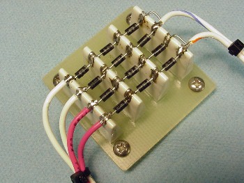 ] ]
The diode strings replace both of the original 5U4 and 5R4 rectifier tubes.
|
 |
|
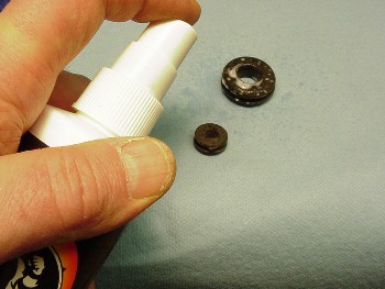
There are two grommets in the 516F-2 that ferry wires through the chassis. A dab of Armour-All restored them to like-new condition. |
| Next I mounted the transformer, chokes and other components on the chassis. The new filter capacitors didn't fit in the existing clamps, so I drilled out the clamps and replaced them with another glass-epoxy board. More Tek terminal strips hold the new capacitors and voltage equalizing resistors, and 8-conductor rotor cable replaces the original interconnecting cable. Now the fun part begins -- wiring up the supply! |
|
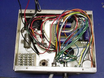 |
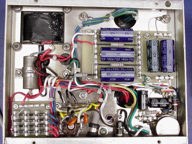
Two evenings later, and the job is done. The diode bank is in the lower left of the photo, and above it is the metal .05 uF resonating capacitor for the HV filter choke. The new circuit board with the filter capacitors and equalizing resistors is mounted on 1/4" metal standoffs in the middle-right of the supply. (Modern metal-film resistors replace the old 270K composition resistors.) The remaining octal tube socket along the bottom now is wired to accept a plug-in relay. The bias circuitry with its original adjustment pot is in the lower right.
|
 |
|
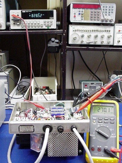
Finally it comes time for the smoke test. Fortunately, everything seems to work fine and, best of all, the voltages are comfortably with in a few percent of Collins' specified values. The plug-in relay is a DPDT Magnecraft model 750XBXM4L-120A (Mouser p/n 528-750X4-120A, $11.50), with a 120VAC coil and dual 16 Amp contacts. It is activated by the transceiver power switch, and takes the burden off the switch contacts. The relay features an LED that lights when the DPDT contacts close and a push bar to activate them manually. I soldered 150V Varactor surge protectors across the relay contacts (at the tube socket pins) to limit arcing caused by the inductive kick of the transformer at turn-off.
|
|
Here is the completed supply, with its shiny new iron, control relay and mostly new parts. About the only components remaining from the original supply are the small 1H filter choke, the bleeder resistors and cage, and the bias adjustment pot. After the photo was taken, I added a bottom plate to keep fingers out of the innards.
|
|
|
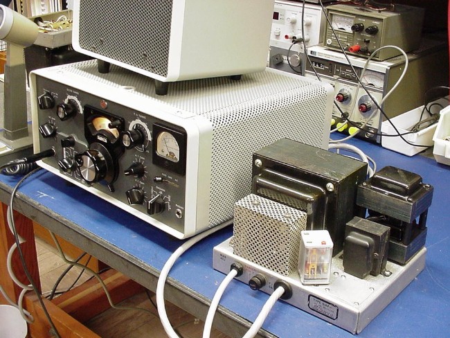
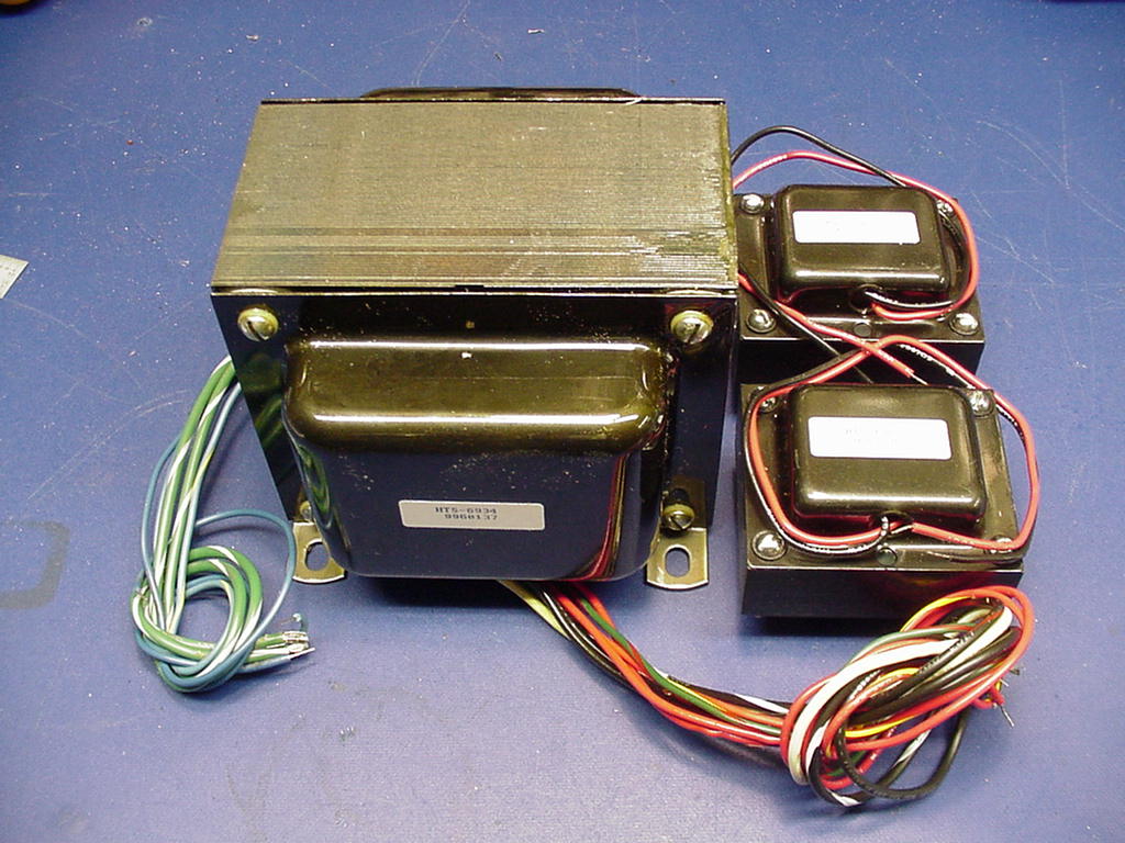
And lastly, before buttoning up the supply in its cabinet, is an on-the-air test. After adjusting the KWM-2A bias for 40 mA resting current, and zeroing the S-meter and ALC to allow for the lower voltages, my trusty KWM-2A seems very happy. I'm very happy too, knowing that this classic vintage rig will run cooler and that the rehabbed supply will almost certainly outlast its owner. I'm really grateful to Bill K3PGB for taking the initiative to remanufacture the 516F-2 transformers, and to the Heyboer Transformer Company for their excellent product.
|
|

|
|
 
|
|
|
|

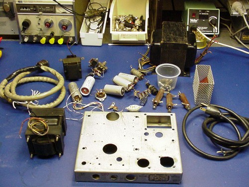
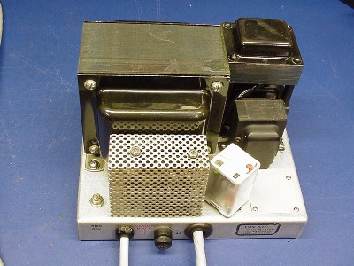
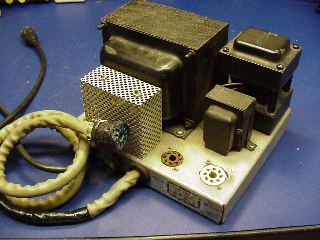 Here is the original "junker" 516F-2 that was the starting point for this project. It had a bad power cord and interconnecting cable, a poorly installed replacement tube socket, chipped connectors and innards that were, well, best not talked about. I decided there wasn't much point in trying to turn this ugly duckling back into the Cedar Rapids swan it once had been.